Active Low Pass Filter
CONTROLS
Resistance (R1) : kΩ
Feedback Resistance(Rf) : kΩ
Resistance (R) : kΩ
Capacitor( C) : µf
Input Voltage (Vin) : V
Frequency (Freq) : Hz
Feedback Resistance(Rf) : kΩ
Resistance (R) : kΩ
Capacitor( C) : µf
Input Voltage (Vin) : V
Frequency (Freq) : Hz
INSTRUCTION
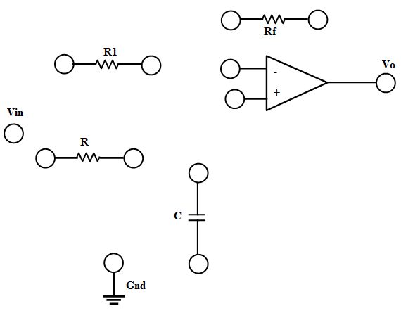
- Connect the components as mentioned below:
L1-L8, L3-L4 or L4-L5, L3-L5, L6-L10 or L6-L9, L9-L10, L7-L13, L2-L12, L11-L12.(For eg. click on 1 and then drag to 8 and so on.) - Click on 'Check Connection' button to check the connections.
- If connected wrong, click on the wrong connection. Else click on 'Delete all connection' button to erase all the connections.
- Set Resistance(R1)=10 KΩ.
- Set Resistance(Rf)=10 KΩ.
- Set Resistance(R)=15 KΩ.
- Set Capacitor(C)=0.01 µF.
- The source voltage (Vin) is set to 10V.
- Keeping source voltage constant, vary the frequency from 50 Hz in regular steps.
- Click on "Add to Table" button to add the readings to the table.
- Vary the Frequency by keeping the resistances and capacitance constant.
- Select "Plot" button to plot the frequency graph or the phase graph of the RC frequency, Frequency(Hz) along X-axis and Magnitude along Y-axis.
- Click on "Clear" button to take another set of readings.
EXPERIMENTAL TABLE
| Serial No. | Frequency(Hz) | Magnitude (|vout/vin|) | Phase(theta) | Output Voltage(V) |
|---|
GRAPH PLOT
Print